|
|
Microcontroller unit with Real Time Clock
|
Most applications made with microcontrollers don't have an internal system time (Real Time Clock - RTC) capable of process time and date independently and preserve this information on startup or during reboot. For example, personal computers include a RTC, but routers for home use do not include one. Mobile phones, photo and video cameras usually have a RTC, but some cheap TV sets do not have one included. To know if the device is equipped with a reliable RTC, first you should check if beside the main power supply, it includes also an auxiliary small battery (for example the well known CR2032 on the PC motherboards or CR1220 on the Canon cameras). Many computers now store BIOS settings in non-volatile memories that don't need a battery, but still need one for RTC.
There are also many devices that use network synchronization for keeping time accurately. For date and time synchronization, TV sets use EPG (electronic programming data), mobile phones use data from the cell towers found in immediate area, PC computers and IOT devices use wired Ethernet or Wi-Fi for time sync. However, this synchronization is usually performed with a delay from startup moment. For some applications this could lead to unacceptable errors. For example, a router can have two modes of operation (day and night) and needs to select one by checking the time at startup. The time synchronization is made usually with delay, so the selection will be erroneous. Another example is a device that needs to keep an accurate log of events and data. The logs recorded before time synchronization contain false timestamps.
In 1999, I made a project for a microcontroller unit based on MCS-51 series and
equipped with a RTC - real time clock. This device was designed for fiscal applications, but can be used for any other project which needs accurate and reliable data and event logging.
Specification:
♦ Power supply: 5V /100mA stabilized
♦ Battery for RTC
- 1/2 AA form
- voltage 3.6V
- type Lithium Thionyl Chloride
- low self discharge rate: 10 year shelf life
♦ Microcontroller Atmel 89C55
- 20K Bytes Reprogrammable Flash Memory
- 256 Bytes internal RAM memory
- 32 Programmable I/O Lines
- program memory protection
- three 16-bit timer/counters
- eight interrupt sources
- low power idle and power down modes
♦ 32kB external SRAM
- low power
- backed up by battery (non-volatile)
♦ Real Time Clock Epson RTC72421
- built-in crystal unit
- time (hours, minutes, seconds) and calendar (year, month, day) counter
- frequency tolerance ± 50x10-6
- aging max ± 5x10⁻⁶ / year
- battery back-up function
♦ The serial interface of the microcontroller can be switched by software to communicate with three devices, one at the time
- COM1 and COM2 are TTL RX/TX (external storage, fiscal memory etc)
- COM3 is RS232C compatible (printer, computer etc)
♦ Output for alphanumeric LCD display controlled with 8 bits parallel
♦ Buzzer
♦ One output for electromagnet 24V / 30 mA max (relay, cash drawer etc)
♦ One output for LED
♦ Use of a programmable area logic device - PAL for internal signal decoding and serial communication switch
|
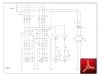
Figure 1
Block diagram |

Figure 2
Schematic diagram |
Figure 3
PAL diagram |
|
Figure 1 contains the block diagram of the microcontroller unit.
The main parts are:
-microcontroller 89C55 with built-in flash memory for program. It is compatible with the industry standard 80C51 instruction set and pinout. The on-chip flash allows the program memory to be reprogrammed in-system or by a conventional non volatile memory programmer.
-high-performance CMOS static RAM organized as 32k words by 8 bits with low power consumption and possibility for back-up on battery
-Real Time Clock with built-in crystal unit allows adjustment-free efficient operation
-Power supply supervisor check main power supply presence and battery charge status and controls microcontroller reset and the switching between power supplies
-Switch for serial communications allows the serial interface of the CPU to be controlled by software to communicate with three devices not simultaneously
Figure 2 shows the schematic diagram. A programmable area logic device is used to minimize the space on printed circuit board PCB. The schematic includes a DC/DC converter ICL7660 with a negative voltage output used to manually adjust the contrast of LCD display. There is also a serial converter from TTL level to RS232C.
Figure 3 contains the schematic diagram and the programming functions for PALCE16V8. This is a CMOS flash second-generation PLD. In this application is used to emulate a circuit with multiple gates. This universal Programmable Array Logic can be electrically erased and provides reconfigurable logic and full testability. Outputs can be configured as registered or combinatorial in any combination.
|
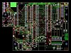
Figure 4
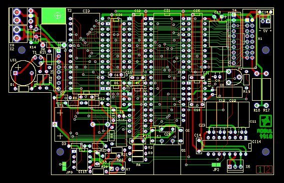
PCB layout
image |

Figure 5
Test program |
|
Figure 4 shows an image of the printed circuit board PCB. Figure 5 is a simple test program for the microcontroller unit.
|
|
Note: If a device does not have a reliable internal RTC to store events correctly, is not suitable for professional applications, even if the manufacturer say so. There are some devices that use GPS or radio for synchronization. This is not a reliable
solution because depends on weather conditions (clouds, rain, strong winds, freezing rain or snow). For critical applications, you should know that GPS and radio synchronization are vulnerable to spoofing attacks.
Disclaimer: The information on this web site is provided "AS IS", without warranty of any kind.
The author has made the best efforts to ensure the design and the information provided are reliable.
Under no circumstances shall the author be liable for any direct, indirect, incidental, special
or consequential loss, damage, expense or injury incurred or suffered which is claimed
to resulted from use of this site, even if expressly advised of the possibility of
such loss, damage, expense or injury,
including, without limitation, any fault, error, omission, interruption or delay with respect thereto.
Links:
[1] - Atmel 89C55 datasheet
[2] - Epson RTC72421 datasheet
[3] - Vantis PALCE16V8 datasheet
|
|
|
