Digital clock

This desk clock is made by using the printed circuit board (PCB) from an old wrist LCD watch (figure 1), a LED display (figure 8) and an driver (figure 5) to adapt the PCB (figure 3) to the LED display (figure 7). I made this desk clock in 1989.

The quartz crystal (figure 4) we used has the nominal frequency 32.768 kHz. The frequency tolerance is ±20x10-6 at 25°C. To obtain a better accuracy for the final clock, we used an adjustable capacitor mounted in parallel with the quartz crystal (see figure 10).

Figure 1
Wrist LCD watch
Figure 2
Watch parts
Figure 3
PCB
Figure 4
Quartz crystal

Figures 5 to 9 contain the schematic of the project. The watch has initially a LCD display (figure 9) multiplexed in two sections (roughly the upper and the lower part of the display). The schematic shows a driver section (figure 5) that adapts the signals designated to LCD display to the new LED display. This LED display has a configuration capable to simulate the old LCD part. For that are used four modules of seven segment, one digit LED (see figure 8). The second digit has been used upside-down. In that way, the decimal points of digits 2 an 3 make together the "blinking seconds indicator". Before soldering to final circuit, digits 2, 3 and 4 should be disassembled, their PCB layout modified and then reassembled. The LED modules must be with common anode and not sealed on the back. The necessary layout is shown in figure 8. In essence, each one of the three modules will have two separated anodes after modifications.

Figure 5
Chip and driver
Figure 6
Watch PCB
Figure 7
LED display

Schematic of the driver is shown in figure 5. Each pair of segments is controlled by a comparator. In this circuit section are used single supply, quad comparators type LM339. There are no resistors provided for limiting the current through LED display. The limitation is provided by 339 comparators. The circuits for the two multiplexed lines (anodes) are made with transistors. Figure 6 is showing the power supply schematic.

There are some modifications we made to the original schematic. Figure 11 contains these changes:
-power supply for driver goes from 0 to 3.6 V (instead of 0 to 5 V)
-power supply circuit for watch PCB was slightly modified, the functionality is the same.
-we added capacitors in parallel with quartz crystal. There is also a multi-turn trimmer capacitor for an accurate and stable adjustment of the clock speed.

Figure 8
LCD display
Figure 9
Chip and
power supply
Figure 10
Frequency
adjustment

Diodes EFD108 are germanium diodes. If are not available, can be replaced by Schottky diodes 1N5817. The diodes used in driver circuit at the inputs of 339 comparators can be replaced by 1.5 MOhm resistors as shown in figure 18 (a project made later). The later project has two major advantages: seven segment LED modules do not need to be modified and display is not multiplexed.

Figure 11
Desk clock
Figure 12
Wallet clock
Figure 13
Other display 1

Instead can be found other types of clocks (figure 12, 13) that have LCD layouts as in figures 14, 15 and 16. Datasheet for the clock IC (with 3 1/2 digit dispay) is shown in figure 17.

Figure 14
Other display 2
Figure 15
Other display 3
Figure 16
Clock IC
(PDF)
Figure 17
Other similar
project

Beside the wrist watch PCB, the project contains three more PCBs manually manufactured (figures 18, 19 and 20): base board, display board and a board for connections to watch PCB.

Figure 18
Figure 19
Figure 20

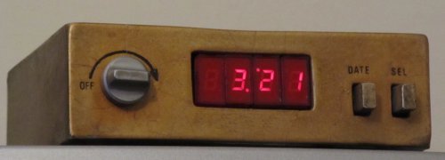
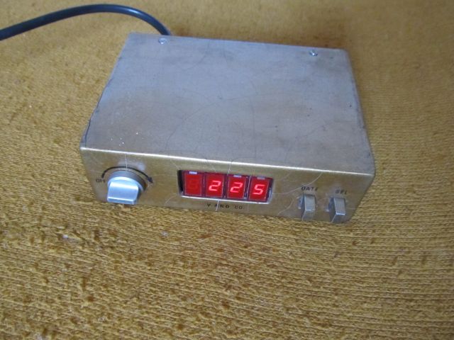
The enclosure has been manufactured using transparent plastic panels, glued together with a plastic glue. When ready, the enclosure has been covered with silver color paint. The rear panel is detachable to enable 
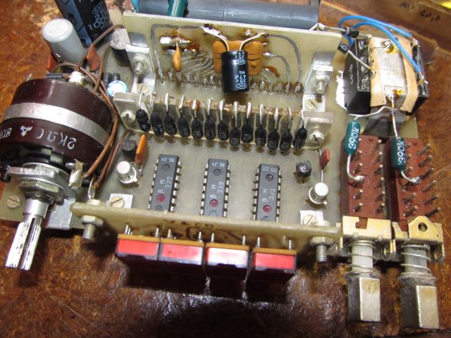
the pulling out of the circuit board. It was kept transparent and small holes has been drilled in it. This is for enabling the frequency adjustment and measuring the battery voltage from outside, without disassembling the clock.

Advantages:
-front panel potentiometer for brightness adjustment
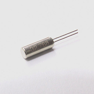
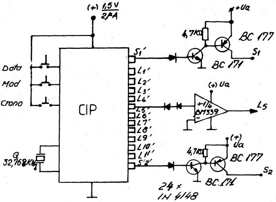
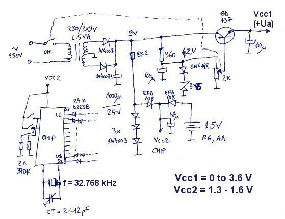
-the clock speed does not depends on power grid frequency. There is an internal quartz crystal driven oscillator
-possibility for accurate adjustment of the clock speed (by adjusting the oscillator frequency)
-powered from mains power supply with low power consumption: 1.42 VA
-the backup battery is in operation only when mains power supply is not available, therefore it last for long time (years)
-after about 30 years of continuous use it still works just fine

Disadvantages:
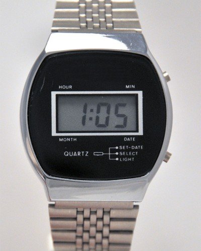
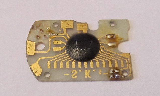
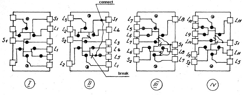
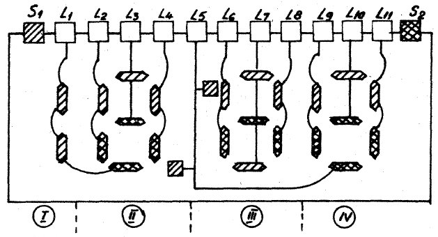
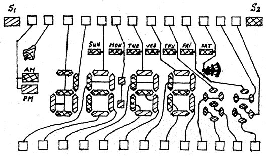
-making modifications to LED modules and connections to watch PCB without damaging the components, require a good soldering iron, accuracy and attention in work

Disclaimer: The information on this web site is provided "AS IS", without warranty of any kind. The author has made the best efforts to ensure the design and the information provided are reliable. Under no circumstances shall the author be liable for any direct, indirect, incidental, special or consequential loss, damage, expense or injury incurred or suffered which is claimed to resulted from use of this site, even if expressly advised of the possibility of such loss, damage, expense or injury, including, without limitation, any fault, error, omission, interruption or delay with respect thereto.

Links:
[1] - RCL Semiconductors Limited - manufacturer of digital watches ICs
[2] - LM339 - quad comparator