|
|

Lead-acid battery charger
with constant current
|
I made this device in 1990. The charger is based on a constant current generator.
The current can be manually adjusted to precise values in 0 to 8 Amps range,
using a potentiometer. User can charge the battery
according to the correct algorithm. It was designed
specifically for 12 V car batteries, but it can be used as well for other
Pb-acid models with voltages between 2 and 12 Volts.
In theory, lead-acid batteries charging should use an algorithm
with three steps (similar to the one applied for lithium-ion batteries).
The charge time is around 8-16 hours and depends on
battery capacity, charge current used and initial charge level.
- First step: the battery is charged with constant current
for a period that takes about half of the total
charging time. Usually first step is performed with a current that have in Amps
10% of the battery capacity in Ah (for example, a 60 Ah battery uses
a charging current of 6 Amps).
- In second step, the voltage
of the battery should be maintained at a level between 2.3 to 2.45 Volts
by adjusting the charge current. It takes about 40% of the
charge time.
- Third step is using a very low charging current until the voltage of the battery goes down
to around 2.25 Volts per cell. This step takes the remaining 10% of the total
charging time.
A "smart charger" for lead-acid batteries that can perform automatically the above mentioned
steps is usually
based on a microprocessor and is expensive.
A constant current charger can be used instead.
On every step, the charging current must be adjusted manually and the battery voltage
must be monitored.
|
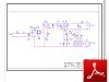
Figure 1
Schematic (PDF) |

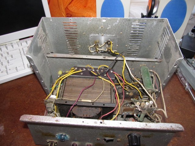
Figure 2 |

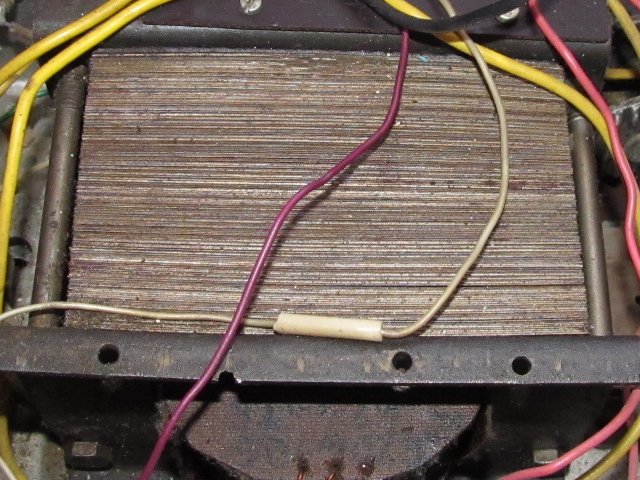
Figure 3
Transformer |
|
Figure 1 shows the schematic of the charger. It was designed by me.
The project contains the following main parts:
Transformer T1 (Figure 3):
-input voltage = 230 V ac
-input frequency = 50 Hz
-output voltage = 20 V ac
-output current = 8 A max.
-power = 250 W (approx.)
-core type: laminated iron-silicon steel alloy, E60, E+I shape
-core area = 60 x 32 mm = 19.2 square cm
-primary coil, number of turns = 620
-primary coil, enamelled copper, wire diameter = 0.6 mm
-secondary coil, number of turns = 62
-secondary coil, enamelled copper, wire diameter = 1.6 mm
Bridge rectifier D1-D4 (Figure 4):
-made with 4 diodes RA220 (200 V, 20 A)
Current generator:
-Q1 and Q2 (Figure 5) are power transistors wired in parallel. Usually, in this
connection type, a resistor in series with each transistor emitter
should be included to balance the current. We made the circuit
with a single emitter resistor (Re), to know the output current by measuring
the voltage of that resistor. We select
from many power transistors of same type, a pair that provide identical gain (hFE).
-Q4, Q3 and Q1/Q2 compose a three stage (triple) Darlington circuit.
-the Darlington circuit with resistor Re and the variable voltage reference
(D4, R1-R3, R5-R7) make a current generator. The current value is manually adjusted with
potentiometer R2.
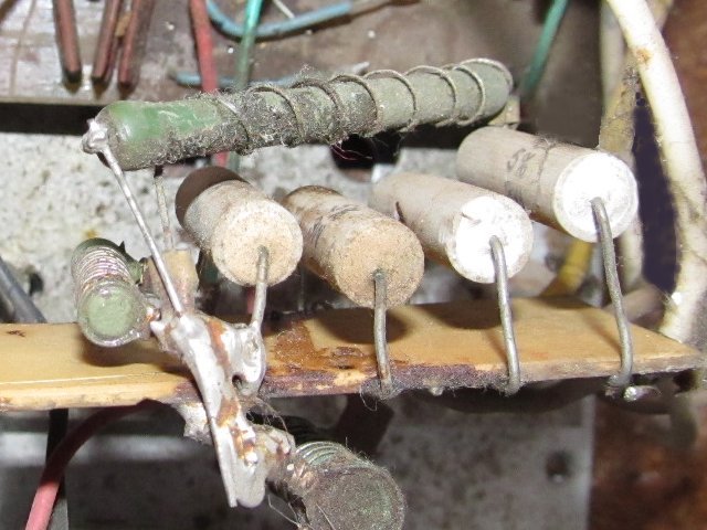
-Resistor Re (Figure 6) was built with several resistors of different values in parallel,
to obtain a value of 0.1 Ohm. This resistor is
serving for current generator and for measuring the charge current.
-A connector with 2 pins wired to Re was provided on the back of the enclosure.
When adjusting the charge current with R2, an external voltmeter must be connected there.
This allow us to know the current value ( for example, a measured voltage of 0.55 V
correspond to 5.5 Amps charging current).
Charge indicator:
-Q6, Q5, D5, C1, R4, R8, R9 provide a charge indicator. The LED D7 starts to light up when
the battery reach the voltage corresponding to the end of the first step.
Reverse polarity protection:
-D6 (Figure 7) and F3 are making together a protection when the battery is connected
with reversed polarity. When such an event occur, the fuse F3 blows and the rest of
the circuit is protected.
|

Figure 4
Bridge rectifier |

Figure 5
Power transistors
on heatsink |

Figure 6
Re=0.1 Ohm |

Figure 7
D6 - KU290 diode |
|
A circular heatsink for Q1 and Q2 made from duralumin
was mounted on top of the enclosure.
Advantages:
-manual adjustment of the charge current in 0 to 8 A range using
a potentiometer
-the complete charging algorithm can be applied with this device
-high reliability and robustness
-protection for reverse connection
Disadvantages:
-low energy efficiency
-An external voltmeter is needed to indicate the charge current (this could be also an advantage,
because it allows us to measure the charge current with higher precision compare
to a panel indicator)
Disclaimer: The information on this web site is provided "AS IS", without warranty of any kind.
The author have made the best efforts to ensure the design and the information provided are reliable.
Under no circumstances shall the author be liable for any direct, indirect, incidental, special
or consequential loss, damage, expense or injury incurred or suffered which is claimed
to resulted from use of this site, even if expressly advised of the possibility of
such loss, damage, expense or injury,
including, without limitation, any fault, error, omission, interruption or delay with respect thereto.
Reference links:
[1] - Wikipedia:
Darlington transistor
[2] - Wikipedia:
Current source
[3] - Wikibooks: Transformer design
|
|
|