|
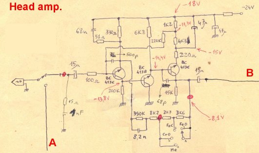
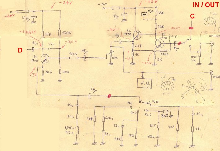
Head amplifier (figure 1) is an implementation of classic NAB/IEC standards for reading tapes. It uses three NPN transistors (compare to other schematics which use only two). This will assure a better open loop gain of the amplifier. The applied negative feedback is according to tape type (selectable by switch).
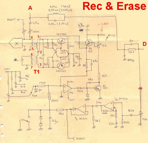
Erase oscillator (figure 2) was made with two 2N2905 transistors and T1 transformer. Signal amplitude is controlled by the supply voltage applied to oscillator (according to tape type). T1 is based on a magnetic ferrite core with the following specification:
-oscillator frequency: 78 kHz
-the amplitude of output signal (to erase head) is according to tape type (selectable by switch)
-magnetic core type: D26 x 16, Al = 3700 nH / square turns
-coil 1-2: 30 turns
-coil 2-3: 30 turns
-coil 4-5: 100 turns
-coil 6-7: 50 turns
-wires: enameled copper, wire diameter = 0.3 mm
Input/Output amplifier (figure 4) is common for play and record. Amplification factor is 10 (10 dB). In record mode there is a potentiometer on each channel (physically placed on front panel) to adjust the recording level.
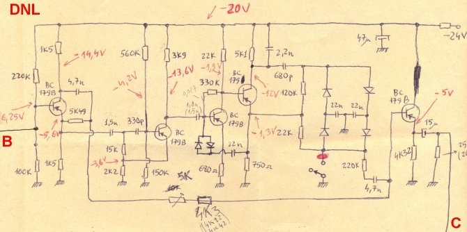
DNL - Dynamic Noise Limiter (figure 3) is an audio noise reduction system originally introduced by Philips in 1971 for use on cassette decks. All recording devices, both analog and digital, have traits that make them susceptible to noise. Noise can be random or white noise with no coherence, or coherent noise introduced by the device's mechanism and electronic components. When using analog tape recording technology, they may exhibit a type of noise known as tape hiss. This is related to the particle size and texture used in the magnetic emulsion that is sprayed on the recording media, and also to the relative tape velocity across the tape heads. The schematic used by me here is in essence a low pass filter dynamically controlled by signal level.
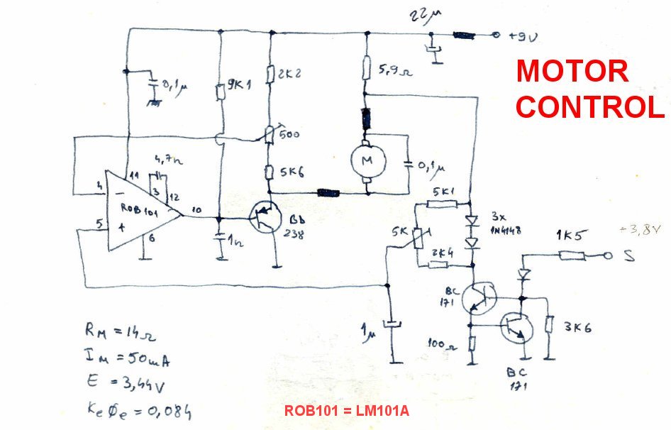
Motor controller (figure 5) is a schematic designed by me after many tests with different configurations. The feedback was optimized to compensate the motor speed variations with load.
VU-meter (figure 6) is based on A277D scale LED indicator integrated circuit. Schematic diagram I used here is from the IC datasheet.
Digital tape counter (figure 7) is composed of:
-a strip band with alternating colors black and white painted on a mechanism wheel
-a LED to illuminate the strip band
-a phototransistor to read reflections on the strip band and convert the alternating black and white colors into 0/1 logical signal
-a frequency divider with three toggle flip-flops
-a monostable multivibrator (74121) to format the tape counter pulse length
-an oscillator (7413)
-one 4-bit parallel shift registers (7495) driven by the oscillator and by the counter pulse. The ouputs are three signals 1/+/- to add or substract an unit on calculator IC
-calculator IC C683D with LED display. The increase or decrease logical commands are received from the shift registers
-a retriggerable monostable multivibrator (74123) to stop the motor when the tape reaches one end
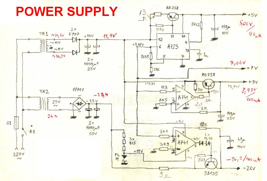
Figure 8 shows the power supplies of the system. The output DC voltages are: -26V, +9V and +5V. Also there is an output reference voltage of 7V.
|